
Features of Electronic Eye Circuit
An Electronic Eye Circuit mimics the function of a human eye by detecting changes in light intensity and triggering a response, typically used in security, automation, and smart lighting systems.

Figure 1. Key Functional Highlights of an Electronic Eye Circuit.
Light Sensing Mechanism
- The Electronic Eye Circuit is designed to detect changes in light intensity. Figure 1 shows Key Functional Highlights of an Electronic Eye Circuit
- It primarily uses an LDR (Light Dependent Resistor).
- In bright light, the LDR has low resistance.
- In darkness, the LDR has high resistance.
- This behavior helps the circuit sense the presence or absence of light, just like a human eye.
Automatic Response System
- The circuit reacts automatically when the light level crosses a certain threshold.
- Example: Turns ON a bulb when it gets dark and OFF when it’s bright.
- This automatic switching is often achieved using transistors, comparators, or relays.
Sensitivity and Control
- The sensitivity of the circuit can be adjusted using a potentiometer.
- This allows the user to:
- Define how dark or bright it should be before triggering.
- Customize the behavior for different environments.
- Useful in both indoor and outdoor lighting systems.
Simple and Affordable Circuit Design
- Components commonly used:
- LDR
- Resistors
- Transistors or operational amplifiers (e.g., LM358)
- Diodes
- Relay (for heavy load control)
- The circuit is low-cost, compact, and easy to build.
- Ideal for DIY projects, school experiments, and home automation.
Applications and Real-Life Usage
- Smart lighting: Streetlights, garden lights, corridor lights.
- Security systems: Trigger alarms when someone blocks a beam.
- Energy saving: Prevents lights from staying ON unnecessarily.
- Industrial monitoring: Detect light failure or environment changes.
Reference:
- https://www.digikey.in/en/articles/why-and-how-to-effectively-use-electronic-fuses
Cite this article:
Nandhinidwaraka S (2021),Features of Electronic Eye Circuit, AnaTechMaz, pp. 39
Recent Post
-
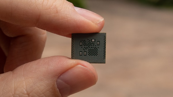
The Technology of 5nm Processor
The 5nm (nanometer) processor technology represents a major advancement in semiconductor...
-

AI in Cloud Computing
AI in Cloud Computing is the integration of artificial intelligence (AI) capabilities into cloud...
-

AI shopping system
An AI shopping system is a technology-driven solution that uses artificial...
-

An Overview of Artificial Eye
An artificial eye is a technological device designed to restore or enhance vision in....
-

Blue Brain Technology
The Blue Brain Project was a Swiss neuroscience initiative launched in May 2005 at EPFL....
-
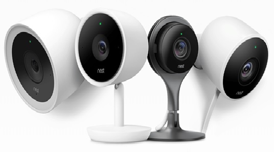
Camera Motion Sensor System
A Camera Motion Sensor System is a surveillance or monitoring system that combines a camera....
-
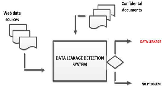
Data Leakage Detection System
A Data Leakage Detection System is a security mechanism designed to identify, monitor, and....
-
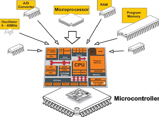
Difference Between Microprocessor and Microcontrollers
A microprocessor is essentially the brain of a computer system—it is a central processing...
-
Features of Electronic Eye Circuit
An Electronic Eye Circuit mimics the function of a human eye by detecting changes in light.....
-

Generative Artificial Intelligence (AI)
Generative AI refers to a subset of artificial intelligence techniques that enable machines....
-
Overview of Clockless Chips
Clockless chips, also known as asynchronous chips, represent a shift from traditional.....
-
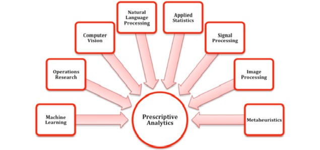
The Methods of Prescriptive Analytics
Prescriptive analytics is the phase of data analytics focused on recommending specific actions...
-
The Artificial Neurons on Silicon Chips
In 2021, scientists made a breakthrough in developing artificial neurons built on silicon chips...
-

The Invention of Crypto Currency
Cryptocurrency wasn’t actually invented in 2021 — it began much earlier — but 2021 was a landmark...
-

The Platform of Bitcoin Mining
Bitcoin mining is the process by which new bitcoins are created and transactions are verified.....