
Buck-Boost Converter Circuit
A buck-boost boost converter can supply a regulated DC output from a power source delivering a voltage either below or above the regulated output voltage. A buck-boost converter circuit combines elements of both a buck converter and a boost converter, however they are often larger in footprint than either alternative. The below simplified circuit diagram shows a typical flow of current during a switching event through a buck-boost converter. [1]
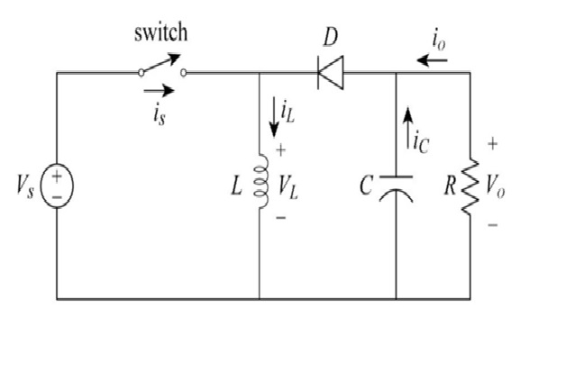
Figure 1. Buck-Boost Converter Circuit
Figure 1 shows The basic circuit of buck–boost convert consists of a diode (D), an inductor (L), and a capacitor (C). The switch used in the circuit is a metal-oxide semiconductor field-effect transistor (MOSFET). The load in the circuit is indicated by the resistor, which is connected across the filter (capacitor). The diode acts a second switch in the circuit. The controlled switch (MOSFET switch) can be turned ON and OFF by the pulse width modulation (PWM) technique. [2]
Modes Of Buck Boost Converters
There are two different types of modes in the buck boost converter. The following are the two different types of buck boost converters.
- Continuous conduction mode.
- Discontinuous conduction mode.
Continuous Conduction Mode
In the continuous conduction mode the current from end to end of inductor never goes to zero. Hence the inductor partially discharges earlier than the switching cycle.
Discontinuous Conduction Mode
In this mode the current through the inductor goes to zero. Hence the inductor will totally discharge at the end of switching cycles.
Applications of Buck boost converter
- It is used in the self regulating power supplies.
- It has consumer electronics.
- It is used in the Battery power systems.
- Adaptive control applications.
- Power amplifier applications.
Advantages of Buck Boost Converter
- It gives higher output voltage.
- It gives higher output voltage.
- Low voltage on MOSFETs [3]
The buck–boost converter is a type of DC-to-DC converter (also knownas a chopper) that has an output voltage magnitude that is either greater than or less than the input voltage magnitude. It is used to “step up” the DC voltage, similar to a transformer for AC circuits. It is equivalent to a flyback converter using a single inductor instead of a transformer. Two different topologies are called buck–boost converter. DC-DC converters are also known as choppers. [4]
References:
- https://recom-power.com/en/rec-n-an-introduction-to-buck,-boost,-and-buck!sboost-converters-131.html?0#buck-boost-converter
- https://www.chegg.com/homework-help/definitions/buck-boost-converter-4
- https://www.elprocus.com/buck-boost-converter-circuit-theory-working-applications/
- https://www.electrical4u.com/buck-boost-converter/
Cite this article:
Thanusri swetha J (2021), Buck-Boost Converter Circuit, Anatechmaz, pp. 39
Recent Post
-
A Process of Dual Core Processor
A dual core processor for a computer is a central processing unit (CPU) that has two separate cores on the same...
-
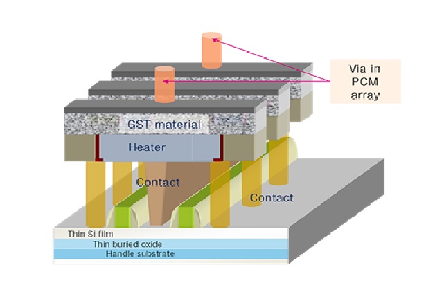
Advanatges of Phase Change Memory – PCM
Phase change memory (PCM) is a type of non-volatile RAM that stores data by changing the state...
-
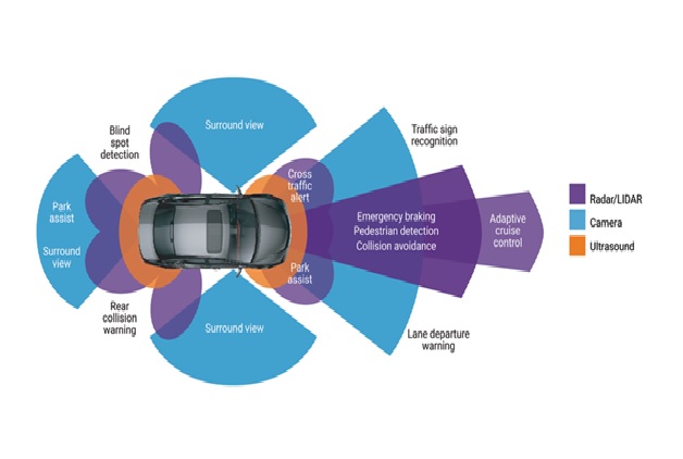
Advanced Driver Assistance System (ADAS)
Advanced driver assistance systems, or ADAS, is the term used to describe the growing number of safety...
-
Advantage and disadvantage of Scrum Methodology
Scrum is an agile development methodology used in the development of Software based on an iterative...
-
Advantages and Applications of Holographic Memory
Holographic memory a storage device that records binary information in the form of holograms...
-
Advantages of Flywheel Energy Storage System (FESS)
Flywheel energy storage systems (FESS) use electric energy input which is stored in the form of kinetic energy...
-

An Overview of Virtual keyboard
It is used as an alternative to a traditional keyboard and can be accessed through various interfaces...
-

Benefits of Brain-Chip Technology
2D in-vitro models such as regular Petri dishes, can form mono-layers of the target cells and can be used for high-throughput...
-
Buck-Boost Converter Circuit
A buck-boost boost converter can supply a regulated DC output from a power source delivering a voltage either below or above...
-

Dangers of Cyberbullying Detection System
Cyberbullying is a relatively new form of bullying. This bullying is committed by means of an electronic act...
-
Development of Gi-Fi Technology
GI-FI will helps to push wireless communications to faster drive. For many years cables ruled the world. Optical fibers...
-
Diamond Chip Technology
Diamond Chip or carbon Chip is an electronic chip manufactured on a Diamond structural Carbon wafer. OR it can be also...
-

Features of E-Ball Technology
E-Ball Technology is the latest innovation in the Computer domain, dwindling the size of computers as never before...
-

Features of Google Glass
Google Glass is Google’s latest product that hails a new generation of tech gadgetry in the form of augmented reality eyeglasses...
-

Features of R Programming
R is one of the open-source Big Data Technologies and programming languages. The free software is widely used for statistical computing...