
Unified Modeling Language (UML)
UML, short for Unified Modeling Language, is a standardized modeling language consisting of an integrated set of diagrams, developed to help system and software developers for specifying, visualizing, constructing, and documenting the artifacts of software systems, as well as for business modeling and other non-software systems. The UML represents a collection of best engineering practices that have proven successful in the modeling of large and complex systems. The UML is a very important part of developing object oriented software and the software development process. [1]
Figure 1. Unified Modeling Language (UML)
Object Oriented Concepts Used in UML
- Class – A class defines the blue print i.e structure and functions of an object.
- Objects – Objects help us to decompose large systems and help us to modularize our system. Modularity helps to divide our system into understandable components so that we can build our system piece by piece. An object is the fundamental unit (building block) of a system which is used to depict an entity.
- Inheritance – Inheritance is a mechanism by which child classes inherit the properties of their parent classes.
- Abstraction – Mechanism by which implementation details are hidden from user.
- Encapsulation – Binding data together and protecting it from the outer world is referred to as encapsulation.
- Polymorphism – Mechanism by which functions or entities are able to exist in different forms.
Types of UML diagrams
UML uses elements and associates them in different ways to form diagrams that represent static, or structural aspects of a system, and behavioral diagrams, which capture the dynamic aspects of a system.
Structural UML diagrams
- Class Diagram The most commonly used UML diagram, and the principal foundation of any object-oriented solution. Classes within a system, attributes and operations and the relationship between each class. Classes are grouped together to create class diagrams when diagramming large systems.
- Component Diagram Displays the structural relationship of software system elements, most often employed when working with complex systems with multiple components. Components communicate using interfaces.
- Composite Structure Diagram Composite structure diagrams are used to show the internal structure of a class.
- Deployment Diagram Illustrates system hardware and its software. Useful when a software solution is deployed across multiple machines with unique configurations.
- Object Diagram Shows the relationship between objects using real world examples and illustrates how a system will look at any given time. Because data is available within objects, they can be used to clarify relationships between objects.[3]
References:
- https://www.visual-paradigm.com/guide/uml-unified-modeling-language/what-is-uml/
- https://www.geeksforgeeks.org/unified-modeling-language-uml-introduction/
- https://www.lucidchart.com/pages/what-is-UML-unified-modeling-language
Cite this article:
Thanusri swetha J (2021) Unified Modeling Language (UML), AnaTechMaz, pp. 55
Recent Post
-
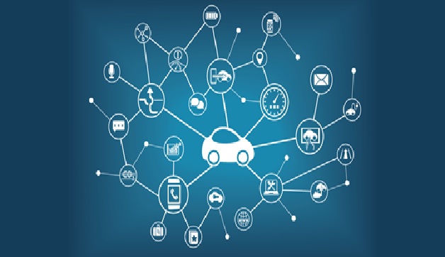
Technologies of Connected Car
A connected car is one that has its own connection to the internet, usually via a wireless local area network (WLAN)...
-
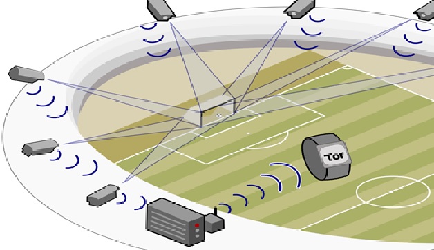
Technologies of Goal-line
Goal-line technology in football is a technology system used to determine whether a ball has crossed the goal line or not...
-
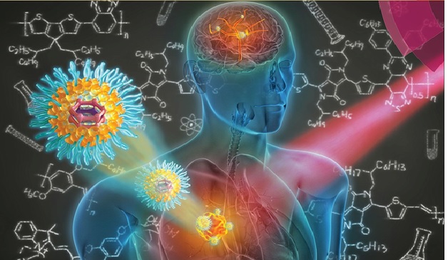
The Application of Nanotechnology in Nanomedicines
Nanomedicine is defined as the medical application of nanotechnology. Nanomedicine can include a wide...
-
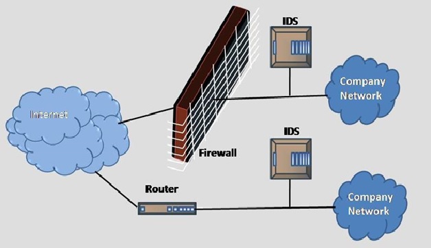
The Methods of Intrusion Detection System
Intrusion detection systems are designed to identify suspicious and malicious activity through network...
-
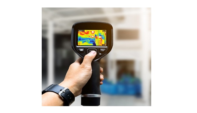
The Thermal and Infrared Imaging Technology
Thermal imaging is a method of using infrared radiation and thermal energy to gather information about objects...
-
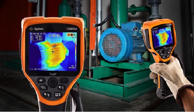
Thermography in engineering
Thermography involves the use of thermal imagers, which are sophisticated devices that measure the natural emission...
-
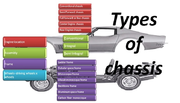
Types of Chassis Frames
Chassis frame is the basic frame work of the automobile. It supports all the parts of the automobile attached to it...
-
Types of Stepper Motor
Stepper Motor is a brushless electromechanical device which converts the train of electric pulses applied...
-

Types of Tamper Resistance
Tamper resistance is the ability of a device to defend against a threat that has the objective to compromise the device...
-
Unified Modeling Language (UML)
UML, short for Unified Modeling Language, is a standardized modeling language consisting of an integrated set of diagrams...
-
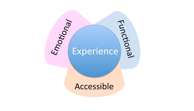
Values of Total Experience
Total experience (TX) is a strategy that creates superior shared experiences by interlinking the user experience...
-
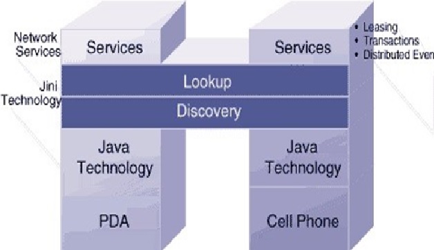
Works of Jini Technology
Jini is a service-oriented architecture that defines a programming model that both exploits and extends Java technology...
-
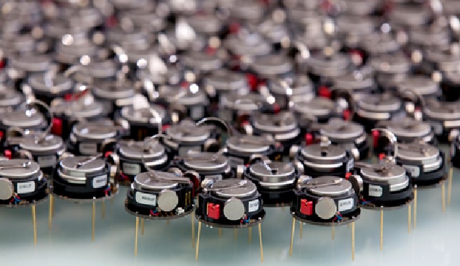
Overview of Swarm Robotics
Swarms typically consist of many individual, simple, and homogeneous or heterogeneous agents (Dorigo and Birattari...
-
Continuous Glucose Monitoring (CGM Technology)
A CGM is a compact medical system that continuously monitors your glucose levels in more or less real time...
-
Digital Humans
Digital human technology takes artificial intelligence (AI) applications to a whole new level. It purports that you can have 3D...